
There can be numerous good reasons to use a computer-controlled microvalve: with low dead volumes and fast switching times they can be used for millifluidics, microfluidics or automation. Two common pitfalls are the driving electronics and the mechanical connection of the valve with the circuit. In this post I detail how to build a stackable manifold with Luer connectors for microvalves driven by a digital signal. Download all conception files for easy replication!
Rationale
Connecting multiple electrovalves altogether to form an hydrolic circuit is often not as simple as it seems. Using soft tubes will rapidly lead to a ratsnest and, more importantly, create large volumes between the valves. As, the null velocity at the tubes inner walls retains products, such volumes can lead to unexpectedly long transients (e.g. see the discussion in these supplementary materials, pages 10-12).
Rigid manifolds can adress these issues, but their design and manufacturing turns out to rapidly grow in complexity and cost with the number of microvalves. This is how I ended up designing a low-cost, stackable manifold with standard connectics (Luer) that can be used in many projects. Each elementary brick of the system supports one three-way valve with an input
Here is a scheme of the system:
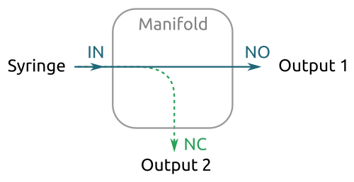
Main components
There are three main components in this system: the microvalve, the manifold and the electronics. Let's review each of them independently:
The microvalve
I purchased the microvalves from The Lee company, and more specifically I choosed the LHDA0531115H solenoid valve with soft tube ported style:
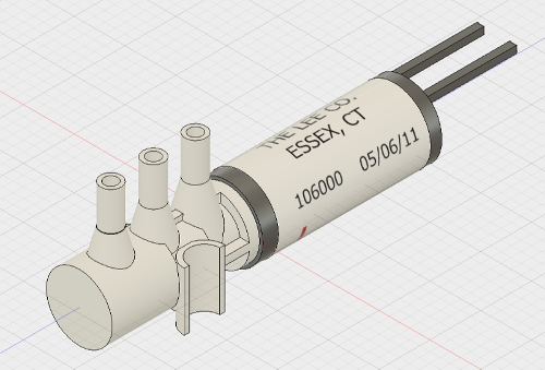
This company also proposes different plug-in styles but I find the soft tube style more versatile as it can be used very rapidly by just connecting tubes on it during test phases. And as we will see in the sequel, the soft tube style can also be plugged into a manifold, so why hesitate?
The 3D model has been designed with Fusion 360 and is freely available on A360 and on GrabCAD.
The manifold
The manifold has been designed with Fusion 360 and then realized with a 3D printer.
A Form 2 3D-printer has been used for this job. I have also tried with a standard wire-feed printer but the inner channels were clogged.
Here are some images of the manifold:
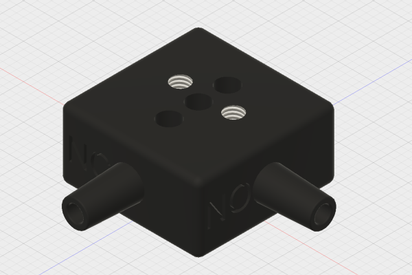
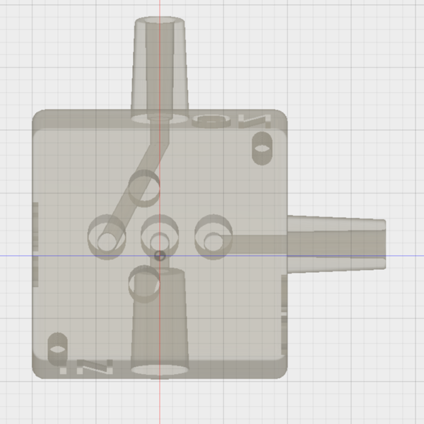
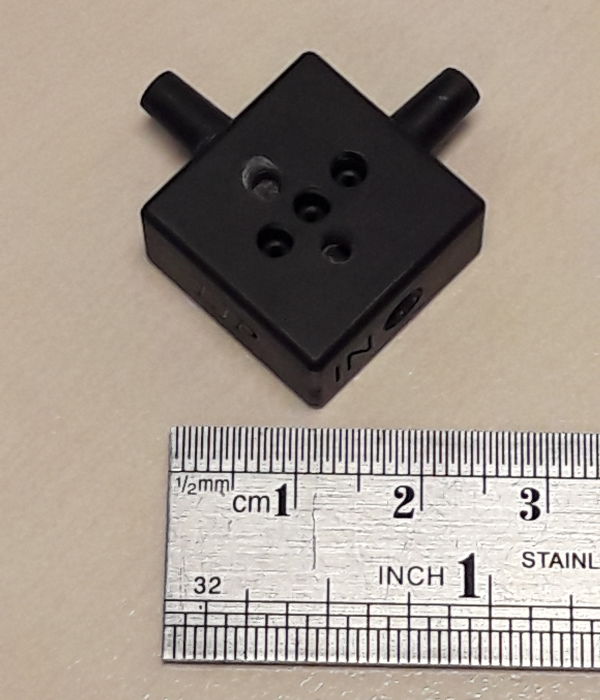
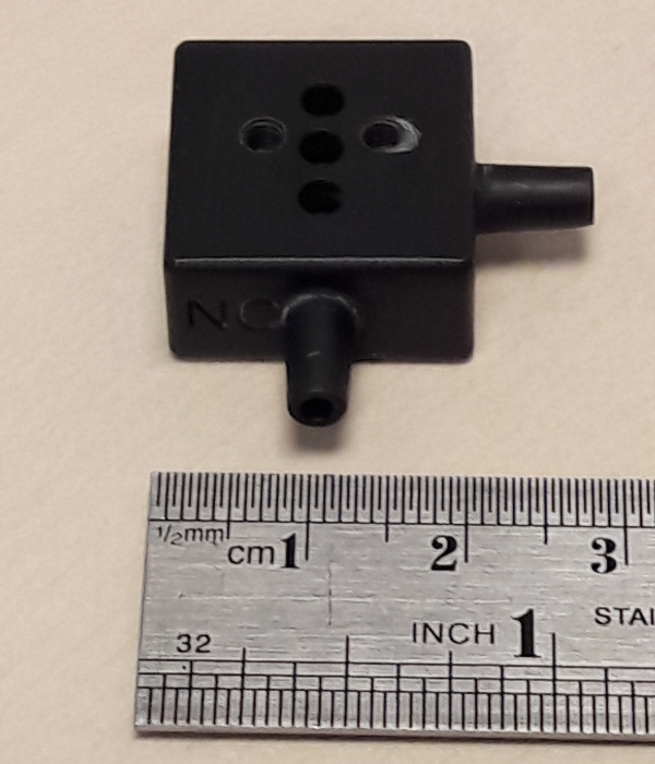
The two M3 (top, to fix the valve) and the two M2 (bottom, to fix the PCB) threaded holes have been threaded manually after impression. However, as the resin is rather soft one can directly insert the screws to form the thread.
The 3D model is freely available on A360 and on GrabCAD.
The electronics
The micrivalve manufacturer proposes many driving circuits, and I've been using a commutator with a NPN transistor:

The 5V power source should hold 110mA per valve. Note that there are also 12V (ref. LHDA1231115H) and 24V (ref. LHDA2431115H) version of the same valve, but as the consummed power remains the same (550mW) they can be operated at 50mA and 25mA, respectively.
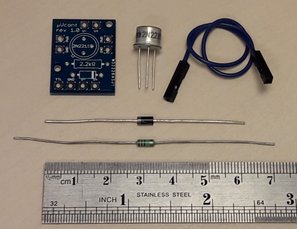
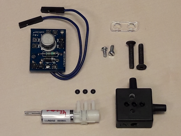
Then, for each valve, you will need:
A NPN transistor. I used a 2N2219 (ref. Mouser 610-2N2219A)
A 2.2kΩ resistance (e.g. ref. Mouser 71-CCF072K20JKE36)
A diode. I used a diode Zener (ref. Mouser 512-1N4007) as it was all I had in stock, but virtually any standard diode would do the job as well
A 6" female-female jumper wire, to connect the valve to the circuit (e.g. ref. Sparkfun PRT-10898).
A PCB chip, as described below (or a standard prototyping board for through-hole soldering if you don't want to order the PCBs).
Optionnally: headers to connect jumper wires for power input and/or control logic (e.g. ref. Sparkfun PRT-00116 or Mouser 474-PRT-00116)
The printed circuit board (PCB) has been designed with Eagle, the files of the project being available here. It has been realized by PCBWay, a chinese manufacturer that proposed a low price (50€ for 50 chips) for a good quality result and a very reasonable 6-days delivery time. The gerber files for production are available here.
Here are some picture of the chips before and after soldering:

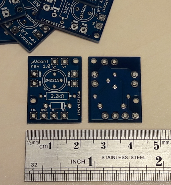
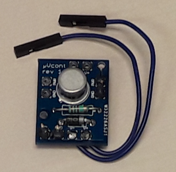
Soldering on the PCB is quite straightforward: as the components are drawn on the silkscreen, there is no chance to solder the transistor or the diode the wrong way. More care must be taken if one solders the parts on a stripped prototyping board.
The jumper wire should be cut in two equal parts, stripped and soldered onto the PCB at
Assembly
Once you have all the parts, the assembly is quite simple:
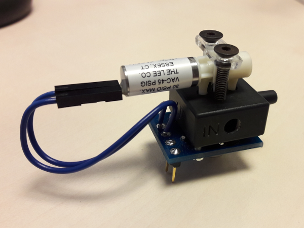
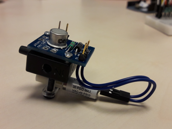

The valve is not polarized, so it does not matter which pin you connect to
During assembly I have used three small torical joints to prevent leaking at the contacts between the valve hoses and the manifold. They are made out of FKM 80 and have a small radius $r=510\mu m$ and a large radius of $R=740\mu m$ (ref. Bramer 24870, not available online you have to ask for a quote).
I have also laser-cutted a small piece of plastic to hold the M3 screws. It is made out of a 3mm-thick PMMA plate, and the schematic can be downloaded here.
Have fun !
Comments
No comments on this post so far.

Leave a comment